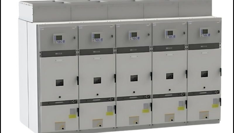
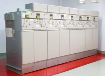
In this modern era of technology, the power distribution depends entirely on the design of switchgear panels. A small defect or any flaw can cause damage not only to the panels but also to the machine and infrastructure. To avoid overheating, nuisance tripping, and faults, it is important to thoroughly understand the design principles of switchgear panels during manufacturing.
When loading calculations for thermal performance levels and protection coordination, every detail is vital to safety, efficiency, and system stability. Many engineers, when selecting switchgear panels, not only focus on ratings and specifications but also deeply consider thermal behavior, fault-withstanding capacity, and system coordination. The article helps you understand the key principles for designing a safer, more reliable, and smarter switchgear panel.
Why Switchgear Design Impact System?
The switchgear not only protects the system but also controls the entire electrical distribution system. The design plays an important role as it determines how power is being distributed, protected, and isolated. A well-designed switchgear is important as it shows the following points:
- Safe handling of faults: Fault detection isolated the faulty section.
- Stable operation under normal conditions: Whenever a fault or damage occurs, the system maintains stable operation without overheating or voltage drops.
- Minimal downtime: The whole system is not affected by the damage or fault, only the affected areas trip.
The poor design exposes many hidden risks. So it is important to select the right switchgear design as safety and equipment lifespan are directly concerned. Switchgear panels must provide efficient thermal performance, as power losses and reduced efficiency result from excess heat. You can read more about this in the guide on energy-efficient switchgear panels, which covers design improvements targeted at minimizing energy losses in actual systems.
Load Analysis and Fault Level Calculations
The load analysis and fault-level calculations are considered the foundations of design. Before selecting any component, it is essential to determine the system’s load capacity and the fault current that can flow, as it is the backbone of the entire switchgear system.
Load Analysis
In load analysis, all components should be properly sized in accordance with the standards. It includes the busbars, breakers, and cables. In real time, not all loads can be operational simultaneously. That’s why many engineers use the demand-and-diversity factory.
- When calculating the load, it is essential that the equipment operates within safe temperature limits, that there is no unnecessary oversizing, and that the system remains stable.
- Factors such as busbar and cable overheating and frequent breaker trips should not be ignored.
- The 3-phase current formula provides the actual current required to size breakers and busbars. It also helps to prevent overheating and under sizing. For calculating the 3-phase Load Current, the following formula is used:
I = P / (√3 × V × PF)
Here, I is for current, P is for power in Watts, V is for Voltage in Volts, and PF is for Power Factor.
Fault Level Calculation
The fault current is defined as the maximum current during the short circuit. And this current value is higher than the normal current. The design of the switchgear panel should be robust enough to handle this current fluctuation. It is considered to be the most critical safety parameter in the design.
- As the value of current changes during the fault, it is important to calculate this value, also known as the transformer’s internal impedance. The formula is stated as:
ISC = (IFL / Z%) × 100
Here ISC is the fault current, IFL the full-load current, and Z% is the transformer impedance. The impedance percentage indicates the voltage required to produce full-load current under short-circuit conditions. Let’s suppose that Z% is 5%, so only 5% of the voltage produces full-load current in a short circuit.
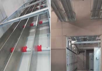
Busbar Design: Current Carrying Capacity and Thermal Limits
The busbars are the main current-carrying backbone of any switchgear panel. They should be able to carry the continuous current without overheating and withstand short-circuit stress.
The under sizing of busbars can increase the risk of failure and fire, increase heat production, and cause insulation to degrade. The busbar design is not only for carrying current but also for heat management, providing a safe, secure, and reliable system.
- Here is a formula for calculating the current flowing through the conductor to generate heat, and that heat generation must remain within safe limits.
I = J × A
Here I is for the current in amperes, J is for the current density, and A is for the cross-sectional area.
Many engineers use this formula because it helps determine busbar size, prevents overheating within the panels, and ensures long-term reliability.
Insulation Design and Clearance Requirement
Insulation plays a vital role, as proper design helps keep electrical parts safe and isolated. Even under harsh weather conditions and high voltages, proper insulation design keeps the system secure.
- The proper insulation design maintains adequate air clearance and creepage distance based on the voltage level.
- Materials such as epoxy resins, polycarbonate, polyolefins, polyester, and ceramic insulators are used. These high-quality materials are selected with the voltage levels, temperature resistance, and environmental conditions in mind.
Thermal Management and Heat Dissipation
Thermal management of switchgear panels is important because electrical components produce heat during operation; these systems remove excess heat efficiently, ensuring that the switchgear panels run safely and reliably.
- Ventilation System: A proper ventilation system was installed, including louvers, vents, and forced-cooling fans. It is ensured that the hot air exits at the top of the panel.
- Overcrowding of Components: The system is designed to provide adequate spacing between busbars, breakers, and cables to prevent overheating. Overcrowding of components traps heat and reduces airflow. A proper layout is implemented to improve cooling.
- Derating: The derating technique is used to reduce the equipment rating when operating at high temperatures. To increase the lifespan of the equipment, this technique is also used.
Conclusion
The effective switchgear panel includes accurate calculations, proper protection, and practical design considerations. From load and fault analysis to insulation and thermal management, every aspect is important, as it ensures that the system is safe and secure. In simple terms, good design not only works under normal conditions but also performs well under faults and stress.


1 Comment
How Switchgear Panels Protect Industrial Equipment from Costly Electrical Failures
June 2, 2026[…] is an industrial switchgear panel playing a main role. Such systems are designed to provide protection, control, power, and isolation […]