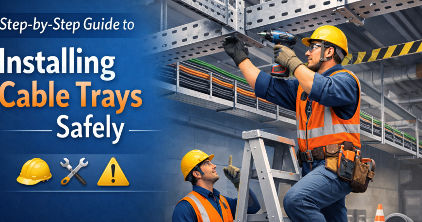
Bilal Switchgear Engineering knows that a messy electrical room is a dangerous one. Cables left hanging or tangled on the floor cause heat. They also cause trips. A proper cable tray is the only way to keep your industrial wiring organized. Following a strict setup guide ensures your facility stays safe from fires.
Planning Your Cable Tray Route and Design
You must start by looking at your site layout. Map out exactly where the wires need to go. Make sure you avoid high-heat areas. Stay away from moving machinery parts. Clearance requirements are very important. You need enough space to pull cables through later. A good design keeps paths straight.
Consider the cable tray load capacity during this phase. You do not want the system to sag. Heavy copper lines are very heavy. Separation between power and data lines is also key. This prevents interference. Interference ruins your signal quality. Proper planning now prevents expensive re-work later.
Choosing the Right Cable Tray Type
Not all environments are the same. A cable tray comes in several styles. There are ladder-type, perforated, and solid-bottom. Ladder trays are great for high-voltage cables. They offer excellent airflow. This prevents the wires from getting too hot. Perforated trays offer more protection from falling debris.
Solid-bottom options are best for sensitive data cables. They provide total shielding from dust. Your environment dictates the material as well. Aluminum is light. It resists rust. Galvanized steel is very strong. It works well for heavy industrial use. Bilal Switchgear Engineering helps you select the best fit for your facility.
Determining the Correct Tray Size
You need to know your cable count first. Measure the total diameter of all cables. They will sit in the tray together. The tray width and depth must allow for growth. Leave about twenty percent for the future. This is a standard rule in Pakistan industrial projects. Never overfill a tray.
Spacing guidelines are there for a reason. If cables are too crowded, they cannot cool down. This leads to insulation damage over time. Distribute the load evenly across the tray surface. It keeps the center of gravity stable. This prevents the mounting brackets from failing.
Selecting Proper Mounting Supports
A cable tray is only as strong as its supports. You can use wall brackets or ceiling hangers. Floor mounts also work. Each one has a specific weight rating. Support spacing usually happens every five feet. If the span is too long, the tray will bend. It might even collapse.
Check the surface where you are mounting. Concrete walls need heavy-duty anchors. Steel beams might need specialized clamps. Make sure every support is perfectly level. Do this before you tighten the bolts. If one bracket is off, the whole run looks crooked. It also loses its strength.
Installing Cable Tray Systems with Precision
Start by assembling the straight sections first. Use proper tray connectors. Get high-quality fittings. Alignment is critical here. You do not want any sharp edges at the joints. Sharp metal can slice through cable jackets. This happens during the pulling process. Use gloves when handling metal.
Use rollers for long-run installations. They help the cable glide smoothly. Once the tray is up, check the level again. Tighten every bolt to the right torque. A loose connector can lead to a failure. This might happen months after the job is done.
Organizing and Laying Cables Neatly
Now you can lay the cables into the cable tray path. Do not just throw them in. Group them by function. Keep different voltage levels separate. Use nylon cable ties or straps to secure them. Do this every few feet. This prevents the wires from sliding. Leave a bit of slack at the ends.
Grounding and Bonding for Safety
Metal cable tray systems must be grounded. This is a major part of safety. Use bonding jumpers at every joint. This ensures a path to the earth. If a wire shorts out, the tray carries the fault safely. It prevents the metal from becoming live. You do not want to get shocked.
Labeling and Documentation
Every run needs clear cable labels. This makes troubleshooting a lot easier. Create a wiring map as you go. Record-keeping is vital for future audits. It helps with facility upgrades. Use documentation best practices. Log the types and numbers of cables in each section.
Inspection and Final Checks
Walk the entire line after you finish. Look for loose clamps. Check for any misalignment. Make sure no section is overfilled. Unsupported spans are a huge risk. Check that the installation follows all safety codes. Site regulations matter. A final check saves lives.
Never Exceed Fill Capacity
As you lay cables, continuously monitor the 40-50% fill ratio. This is not a suggestion—it’s a critical safety requirement. Exceeding fill capacity causes:
- Heat buildup: Cables cannot dissipate heat properly, leading to insulation breakdown
- Mechanical stress: Overcrowded trays put excessive pressure on cable jackets
- Reduced lifespan: Overheated cables fail prematurely (5-10 years vs. 20-30 years)
- Compliance violations: Exceeding fill ratios violates NEC Article 392 and may fail inspection
Use a cable diameter calculation worksheet before installation. Recalculate if you add cables later. When approaching capacity limits (35-40%), plan for a second parallel tray rather than overcrowding the existing one.
Implement Cable Path Documentation During Installation
Create detailed documentation as you lay each cable, rather than after installation is complete. This real-time approach provides several advantages:
Immediate Accuracy:
- Record cable placement, routing, and slack locations while they’re visible
- Note any deviations from original plans and why they were made
- Photograph each section before covering with subsequent cable layers
- Include date, time, and technician name for each installation milestone
Installation Efficiency:
- Identify cable conflicts or interference issues before completion
- Make corrections immediately rather than reworking the entire system
- Verify grounding and bonding requirements at each stage
- Test functionality of critical circuits before final seal-up
Future Maintenance Benefits:
- Technicians can quickly locate and isolate specific cables
- Circuit maps remain accurate for facility expansions
- Reduces troubleshooting time from hours to minutes
- Supports compliance audits and safety inspections
- Enables predictive maintenance when integrated with smart monitoring systems
Documentation Requirements:
- Cable run maps showing exact routing and endpoints
- Fill capacity calculations and percentages per section
- Load weight distribution across support points
- Grounding/bonding verification records
- Expansion joint locations and specifications
- Voltage levels and amperage ratings per section
- Installation photos showing cable placement and spacing
- Completion date and certified installer signature
Digital documentation systems (photos, cloud-based tracking, QR codes) are increasingly standard in modern installations. They provide better accuracy, easier updates, and integration with facility management systems.
Maintenance and Longevity of Cable Tray Units
Routine inspections keep your system running for decades. Check for any signs of corrosion. Look closely at damp spots. Replace broken clamps or ties immediately. Preventive maintenance is much cheaper than failure. The lifespan of your cable tray depends on care.
Reliable cable management starts with a professional cable tray and cable ladder setup. Bilal Switchgear Engineering provides the technical support to get the job done. We offer the best quality products for industrial projects. Our team ensures your infrastructure is safe. Contact us today to start your next installation.
FAQS
What are the guidelines for cable installation?
Follow load limits (40-50% fill capacity) and maintain spacing for proper cooling. Separate high-voltage lines from data cables per NEC Article 392 to prevent electromagnetic interference and signal degradation. Support spacing should follow NEC/IEC standards: every 1.5–3 meters (5–10 feet). Ensure cables are secured every few feet with appropriate fasteners and leave adequate slack at connection points for future maintenance and troubleshooting.
What are the different types of cable trays used in installations?
Main types include ladder (for heavy loads and superior airflow), perforated (for dusty environments with moderate protection), solid-bottom (for sensitive data cables requiring full shielding), and wire mesh (for visibility and lightweight applications). Each type works best for specific environments and load requirements. Material choices include aluminum, galvanized steel, stainless steel, and emerging non-metallic alternatives.
How do I choose the right cable tray for my installation?
Assess your environment (temperature, humidity, corrosion risk), calculate total cable weight and diameter, and determine future growth needs (10-20% spare capacity). For heavy power lines, ladder-type trays are usually best. For data centers and sensitive applications, solid-bottom trays provide better protection. Consult with your cable tray supplier about material selection based on environmental conditions.
What factors determine the correct tray size?
The number of cables, their combined diameter, and the required 40-50% fill capacity are key factors. You also need space for future expansion and adequate heat dissipation. Calculate total cable weight to verify bracket capacity. Follow IEC 61537 guidelines for cable fill ratios to ensure proper thermal management and compliance with standards.
How should cable trays be mounted safely?
Use brackets or hangers rated for the total system weight (tray + cables + future additions). Space supports every 1.5–3 meters per NEC/IEC standards. Verify all mounts are perfectly level before tightening bolts to proper torque specifications. For runs exceeding 30 meters, install expansion joints to accommodate thermal expansion and building movement. Ensure anchors and clamps are appropriate for your structure type.
What are the standard steps in a cable tray installation process?
- Conduct site survey and plan the route
- Calculate cable loads and tray requirements
- Mount and level all support brackets
- Connect tray sections with proper fittings and high-quality connectors
- Lay cables and organize by function and voltage level
- Install bonding jumpers at every joint and ground the system per IEEE 837
- Label all cables using ANSI/ASME A13.1 standards and document the installation
- Perform final inspection and testing for compliance
What are the safety standards and regulations for cable tray installation?
Follow NEC Article 392 (primary standard in North America), IEC 61537 (international standard), IEEE 837 (grounding standards), and ANSI/ASME A13.1 (labeling standards). Comply with local building codes and electrical regulations. Most jurisdictions adopt or reference NEC 2023-2026 requirements. Always verify local requirements with your electrical inspector.
How do smart cable trays improve facility maintenance?
Smart systems with IoT sensors monitor temperature, load, and cable condition in real-time. They enable predictive maintenance by alerting technicians to potential failures before they occur. This reduces unplanned downtime by 30-40% and extends cable lifespan significantly. Real-time dashboards provide visibility into system health and energy usage patterns.
What’s the difference between cable tray and cable ladder systems?
Cable ladders have rungs (like a ladder) for better cable support and visibility. Cable trays have solid or perforated surfaces. Ladders are lighter, offer better airflow, and are preferred for high-voltage heavy cables. Trays provide more cable protection from debris and are better for mixed cable environments with diverse voltage requirements.
What are the expansion joint requirements for large installations?
Install expansion joints on cable tray runs exceeding 30 meters (100 feet) or where the system crosses building expansion joints. Expansion joints allow the tray to move slightly during thermal changes and building settlement, preventing mechanical stress and bracket failure. This is critical for long-term system integrity and safety.
How do I ensure compliance with NEC 2023-2026 standards?
Review Article 392 requirements for your specific application. Key points: support spacing (1.5–3 meters), grounding and bonding (IEEE 837), cable separation (power vs. data), fill capacity (40-50%), proper labeling (ANSI/ASME A13.1), and expansion joint installation. Engage a licensed electrician to verify compliance before final inspection by building authorities.
What sustainable cable tray materials are available?
Options include recycled aluminum, non-metallic composites, corrosion-resistant coatings on steel, and modular systems designed for reconfiguration rather than replacement. These reduce environmental impact and help meet ESG (Environmental, Social, and Governance) requirements while maintaining all safety standards.
What is the maximum cable fill capacity for a tray?
The industry standard is 40-50% of the tray’s cross-sectional area. Exceeding this limit prevents proper heat dissipation, leading to insulation damage and potential electrical faults. This guideline is critical for long cable lifespan and compliance with IEC 61537 and NEC standards. Always calculate total cable diameter and plan for future additions.
How often should cable trays be inspected?
Conduct annual inspections at minimum per NFPA 70B guidelines. In harsh environments (corrosive, high-moisture, high-temperature areas), inspect every 6 months. Check for corrosion, loose clamps, debris accumulation, cable damage, and grounding continuity. More frequent inspections may be required for critical applications like data centers or power facilities.
What causes cable overheating in trays?
Overcrowded trays (exceeding 40-50% fill) prevent air circulation and heat dissipation. Poor ventilation around the tray, inadequate support spacing leading to tray compression, and high ambient temperatures contribute to overheating. Using smart temperature sensors helps detect overheating before insulation damage occurs. Proper tray sizing and cable organization are essential preventive measures.
Can I mix power and data cables in the same tray?
Not recommended. Power cables generate electromagnetic fields that cause interference with data signals, degrading network performance. Best practice is to install separate trays for power and data cables, or use dividers within the same tray. This separation is required by NEC Article 392 and improves both safety and reliability.
How do I handle cable tray installation in outdoor environments?
Use corrosion-resistant materials: aluminum, stainless steel, or galvanized steel with protective coatings. Install water-shedding covers or sloped designs to prevent moisture accumulation. Ensure proper grounding for lightning protection. Inspect more frequently (every 3-6 months) for corrosion. Consider UV-resistant fasteners and supports designed for temperature fluctuations.
What are bonding jumpers and why are they required?
Bonding jumpers are conductive connections installed at every joint between tray sections. They ensure electrical continuity throughout the system, creating a safe path to ground. If a live wire contacts the tray, the bonding system safely carries the fault current to earth, preventing the entire tray from becoming electrically live and causing electrocution hazards.
What is the cost difference between cable tray types?
Ladder trays are typically the most economical for high-capacity applications. Solid-bottom and perforated trays cost 20-40% more due to enhanced protection. Wire mesh offers mid-range pricing with lightweight benefits. Material choice significantly affects cost: aluminum costs 30-50% more than galvanized steel but offers corrosion resistance and lighter weight. Factor in installation labor and long-term maintenance costs.
How do modular cable tray systems save time and money?
Prefabricated modular systems arrive factory-tested and ready for assembly. They reduce on-site assembly time by 40-50%, lowering labor costs. Modular designs allow quick reconfiguration when facility layouts change, avoiding complete replacement. These systems support scalability for growing operations and reduce installation errors through standardized components.
What equipment do I need for cable tray installation?
Essential tools: level (laser or spirit), torque wrench, socket set, tape measure, cable pullers or rollers for long runs, cable strippers (for proper handling), gloves for sharp metal edges, labeling equipment, and safety equipment (hard hat, safety glasses, fall protection). For large installations, scaffolding or lift equipment may be needed. A multimeter is required for testing grounding continuity.
How do I label cables properly according to standards?
Use ANSI/ASME A13.1 standards for label placement, size, and content. Label each cable with: circuit identifier, voltage/amperage rating, destination, and installation date. Use durable, weather-resistant labels. Maintain a master documentation file with circuit maps and cable routing diagrams. Digital documentation systems are increasingly common and help with future troubleshooting and maintenance.
What happens if support spacing exceeds recommended intervals?
Excessive spacing causes tray sagging and deflection, which can lead to: cable damage from sharp bends, mechanical stress on mounting brackets, and potential complete collapse under load. Sagging also compromises grounding continuity. Always follow NEC/IEC standards: 1.5–3 meters (5–10 feet) for metallic trays, adjusted based on tray type, load, and manufacturer specifications.
Are there different requirements for indoor vs. outdoor installations?
Yes. Outdoor installations require weather-resistant materials (stainless steel, coated aluminum), water-shedding designs, UV-resistant fasteners, enhanced grounding for lightning protection, and more frequent inspections (3-6 months vs. annually). Outdoor trays typically cost 40-60% more. Temperature fluctuations require expansion joints at shorter intervals.
How do smart sensors integrate with facility management systems?
IoT-enabled cable trays connect to cloud-based monitoring platforms via WiFi or hardwired connections. Real-time data (temperature, load, voltage) feeds into facility management dashboards. Integration with SCADA systems enables automated alerts and predictive maintenance scheduling. Mobile apps allow technicians to monitor system health remotely. Data analytics identify trends and optimize maintenance schedules.
What’s included in a post-installation inspection?
Verify: proper support spacing and level installation, correct torque on all bolts, proper grounding and bonding continuity (multimeter testing), cable labeling completeness, fill capacity compliance (40-50%), no cable damage or sharp edges, expansion joints installed correctly, documentation and as-built drawings complete, and compliance with NEC 2023-2026 and local codes.
How long should a properly maintained cable tray system last?
With regular maintenance, cable trays typically last 20-30+ years. Aluminum systems resist corrosion naturally. Galvanized steel lasts 15-25 years depending on environment. Stainless steel and coated systems extend lifespan to 30+ years. Regular inspections, prompt repairs, and environmental protection significantly extend lifespan. Poor maintenance can reduce lifespan to 10-15 years or less.
What is Industry 4.0 and how does it affect cable tray design?
Industry 4.0 refers to smart manufacturing with IoT devices, robotics, and automation. It requires: higher cable density, strict separation between power and control signals, real-time monitoring capabilities, quick reconfiguration for changing production lines, and integration with facility management systems. Modern cable trays must support these needs through modular design, smart monitoring, and flexible layouts.
Follow NEMA or NEC standards for grounding and load. Comply with local building codes to ensure workplace safety.