QUICK REFERENCE FACTS — Power Factor Improvement (PFI) Plants
WAPDA/DISCO minimum acceptable power factor: 0.90 lagging (varies by DISCO tariff category)
Typical low power factor penalty: 1 to 2 percent surcharge per 0.01 below the threshold, up to 25 to 30 percent of the bill
Target power factor after correction: 0.95 to 0.99
Capacitor sizing formula: Qc = P x (tan(phi1) – tan(phi2)), where P is real power in kW
Standard capacitor bank voltage rating: 415V / 440V for LV applications, 11kV for MV applications
Detuning reactor frequency (standard): 134 Hz (7% detuning) or 189 Hz (5.67% detuning) for harmonic-rich loads
Capacitor bank connection (3-phase): delta connection standard for LV capacitor banks
Governing standard: IEC 60831-1/2 for self-healing LV power capacitors
Switching stages in automatic APFC panel: typically 6 to 12 steps
Typical payback period for capacitor bank investment: 12 to 24 months
Supplied and installed by Bilal Switchgear Engineering: Yes — through Power Division
Pakistan’s industrial electricity tariffs include penalty clauses for low power factor that can add 10 to 30 percent to a facility’s monthly electricity bill. A 1000 kW industrial facility operating at 0.75 power factor instead of 0.95 is not only paying penalty surcharges but is also drawing approximately 27 percent more apparent power (kVA) than necessary from the supply network, overloading transformers, cables, and switchgear that could otherwise serve substantially more real load.
A Power Factor Improvement (PFI) plant — a capacitor bank system engineered to correct a facility’s power factor toward unity — is one of the highest-return electrical investments available to Pakistani industrial facilities, with typical payback periods of 12 to 24 months. This guide goes beyond the basic concept of power factor correction to cover the actual engineering design process: how to calculate the required capacitor rating, how to select between fixed and automatic correction, why detuning reactors are essential for facilities with variable speed drives, and how to specify a PFI plant correctly for Pakistani industrial conditions.
This article builds on our introductory guide to power factor correction panels by covering the detailed engineering calculations and design decisions required to specify a properly functioning PFI system. It is written by the engineering team at Bilal Switchgear Engineering, an ABB Licensed Manufacturer designing and installing PFI plants for Pakistani industrial facilities since 1978.
Why Pakistani Industrial Tariffs Penalise Low Power Factor
Pakistani DISCOs (LESCO, GEPCO, FESCO, MEPCO, HESCO, and others) measure and bill industrial customers based on both real power consumption (kWh) and maximum demand (kVA). When a facility’s power factor falls below the DISCO’s minimum threshold — typically 0.90 lagging — the additional reactive power (kVAR) the facility draws from the grid increases its kVA demand without contributing any useful work. Since the DISCO’s distribution infrastructure (transformers, cables, switchgear) must be sized for the kVA demand, not just the kWh consumption, low power factor customers impose real infrastructure costs on the network that the penalty surcharge is designed to recover.
The exact penalty structure varies by DISCO and tariff category, but the general principle under NEPRA tariff regulations is a surcharge applied as a percentage of the demand portion of the bill, increasing as power factor falls further below the threshold. For an industrial facility with a poor power factor of 0.70 to 0.75, the cumulative penalty can reach 25 to 30 percent of the total bill — a substantial and entirely avoidable cost.
Worked example: A textile facility with 1000 kW real power demand operating at 0.75 power factor draws 1333 kVA apparent power (1000 / 0.75). The same facility corrected to 0.95 power factor draws only 1053 kVA (1000 / 0.95) — a reduction of 280 kVA, roughly 21 percent. If the demand charge is PKR 1,800 per kVA per month, this reduction alone saves approximately PKR 504,000 per month before any penalty surcharge avoidance is even calculated.
How to Calculate the Required Capacitor Bank Rating
Correctly sizing a capacitor bank requires a specific engineering calculation based on the facility’s actual real power demand and the existing and target power factor. Undersizing leaves residual penalty exposure. Oversizing wastes capital and risks leading (capacitive) power factor, which carries its own penalty structure under most Pakistani DISCO tariffs.
The Capacitor Sizing Formula
The required capacitor bank reactive power rating in kVAR is calculated using the formula: Qc = P x (tan(phi1) – tan(phi2)), where P is the facility’s real power demand in kW, phi1 is the phase angle corresponding to the existing power factor, and phi2 is the phase angle corresponding to the target power factor. The phase angle is derived from the power factor using the relationship: phi = arccos(PF).
This formula can also be expressed using a simplified multiplier table that relates existing and target power factor directly to a kVAR-per-kW multiplier, avoiding the need to calculate phase angles manually for routine sizing work. Engineering reference tables for this multiplier are widely available and are used by Bilal Switchgear Engineering’s design team for rapid initial sizing before detailed simulation.
Worked Calculation Example
Consider a facility with 1000 kW real power demand currently operating at 0.75 power factor, targeting correction to 0.95 power factor. At 0.75 PF, phi1 = arccos(0.75) = 41.4 degrees, so tan(phi1) = 0.882. At 0.95 PF, phi2 = arccos(0.95) = 18.2 degrees, so tan(phi2) = 0.329. Applying the formula: Qc = 1000 x (0.882 – 0.329) = 1000 x 0.553 = 553 kVAR. This facility requires a capacitor bank rated at approximately 553 kVAR to achieve the target 0.95 power factor at the measured 1000 kW load.
Load Profile Analysis
A single sizing calculation based on one measured demand point is adequate for a stable, constant load facility but is insufficient for facilities with variable load profiles — which describes the majority of Pakistani industrial operations. A proper PFI plant design requires analysing the facility’s load profile over a representative period (ideally a full month including peak production periods) to determine the kVAR requirement across the full range of operating conditions, not just at a single snapshot demand reading. This load profile analysis determines whether fixed or automatic capacitor switching is the appropriate design.
Fixed vs Automatic Power Factor Correction
Two fundamentally different approaches to capacitor bank control are used in Pakistani industrial PFI plants, and selecting the correct approach for a specific facility’s load characteristics significantly affects both performance and equipment longevity.
Fixed Capacitor Banks
A fixed capacitor bank provides a constant, unswitched amount of reactive power compensation regardless of the facility’s instantaneous load. Fixed banks are appropriate only for facilities with a highly stable, continuous load profile where the reactive power demand does not vary significantly through the production cycle — for example, a facility with a small number of large, continuously running motors. Fixed banks are lower in cost and simpler in design than automatic systems, but carry a significant risk: if the facility’s load drops substantially (during a shift change, planned shutdown, or process interruption) while the fixed capacitor bank remains connected, the power factor can swing to a leading (capacitive) condition, which itself triggers a separate penalty under most Pakistani DISCO tariffs and can cause damaging overvoltage conditions on lightly loaded networks.
Automatic Power Factor Correction (APFC) Panels
An automatic power factor correction panel uses a microprocessor-based power factor relay to continuously monitor the facility’s actual power factor and automatically switch capacitor steps in and out of circuit to maintain the target power factor across the full range of load variation. Standard APFC panels in Pakistani industrial applications use 6 to 12 switching steps, allowing the controller to closely match the connected capacitance to the actual reactive power demand at any given moment.
APFC is the standard specification for the vast majority of Pakistani industrial facilities because real production loads vary continuously through shift patterns, machine cycling, and process changes. The capital cost premium of an automatic system over a fixed bank is typically recovered within the first year through more precise correction and avoidance of leading power factor penalties during low-load periods.
Detuned Reactors: Essential Protection for Harmonic-Rich Facilities
Modern Pakistani industrial facilities increasingly use variable frequency drives, UPS systems, LED lighting drivers, and other power electronic equipment that inject harmonic currents into the electrical system. Standard capacitor banks without harmonic protection are highly vulnerable to damage and can actually amplify harmonic distortion through a phenomenon called harmonic resonance.
Why Capacitors and Harmonics Conflict
A capacitor’s impedance decreases as frequency increases, while a typical inductive system’s impedance increases with frequency. At a specific frequency determined by the capacitor rating and the system’s short-circuit impedance, these two impedances can become equal, creating a resonance condition where harmonic currents at that frequency are dramatically amplified rather than absorbed. In facilities with significant 5th harmonic content (250 Hz, common with VFD and rectifier loads), an undetuned capacitor bank can resonate at exactly this frequency, leading to capacitor overheating, fuse failures, and equipment damage.
How Detuning Reactors Solve This
A detuning reactor (also called a harmonic filter reactor) is connected in series with each capacitor step, shifting the resonance point of the capacitor-reactor combination below the lowest significant harmonic present in the facility’s load. Standard detuning frequencies for Pakistani industrial applications are 134 Hz (corresponding to 7 percent detuning, suitable for facilities with moderate VFD load) and 189 Hz (5.67 percent detuning, suitable for facilities with lighter harmonic content). The detuning percentage must be selected based on an analysis of the facility’s actual harmonic spectrum — specifying the wrong detuning value provides inadequate protection or unnecessarily reduces the effective reactive power output of the capacitor bank.
Specification Rule — Detuned Reactors for Industrial PFI Systems
Specification rule: Any Pakistani industrial facility with variable frequency drives, UPS systems exceeding 10 percent of total connected load, or significant LED lighting retrofit should specify detuned reactors as standard on any new capacitor bank installation. The additional cost of detuning reactors (typically 15 to 25 percent above the cost of an undetuned bank of the same rating) is minor compared to the cost of capacitor failures and potential switchgear damage from undetected harmonic resonance.
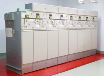
PFI Plant Components and Construction
A complete industrial PFI plant for a Pakistani facility comprises several integrated components, typically housed in a dedicated panel section adjacent to the main LV switchboard or motor control centre.
- Capacitor units: self-healing dry type capacitors built to IEC 60831-1/2, rated for continuous duty at the facility’s nominal voltage with appropriate overvoltage withstand for switching transients
- Detuned reactors: series-connected per capacitor step, sized for the specific harmonic environment of the facility
- Capacitor duty contactors: rated specifically for capacitor switching duty (not standard motor-rated contactors), which must withstand the high inrush current that occurs when a capacitor is energised
- Fuse protection: HRC fuses sized for capacitor protection, coordinated with the contactor breaking capacity
- Automatic power factor controller: microprocessor relay monitoring real-time power factor and managing the step switching sequence with appropriate time delays to prevent excessive switching frequency
- Discharge resistors: integrated into each capacitor unit to safely discharge stored energy after disconnection, a mandatory safety requirement under IEC 60831
PFI Plant Applications Across Pakistani Industry
Textile Mills
Textile spinning and weaving facilities in Pakistan typically operate with hundreds of motors creating substantial inductive load. PFI plants in textile facilities frequently target 600 to 2000 kVAR total correction capacity, installed with detuned reactors due to the prevalence of VFD-driven looms and spinning frames in modern installations.
Cement and Heavy Industry
Cement plants with large kiln drives, fan motors, and crusher equipment represent some of the largest PFI plant installations in Pakistan, with correction capacities frequently exceeding 3000 kVAR at a single facility. The high-inertia, continuous-duty nature of cement plant motor loads makes load profile analysis particularly important to correctly size the automatic switching steps.
Pharmaceutical and Food Processing
Facilities with significant HVAC chiller load (a major source of inductive reactive power) benefit substantially from PFI installation. Pharmaceutical manufacturers in Pakistan with cleanroom HVAC systems running continuously often see power factor improvements that reduce their effective electricity cost by 8 to 15 percent through combined demand charge reduction and penalty avoidance.
PFI Plant Design and Supply from Bilal Switchgear Engineering
Bilal Switchgear Engineering designs, manufactures, and installs PFI plants for Pakistani industrial facilities through our Power Division. Our engineering process begins with a load profile assessment using power quality measurement equipment to capture the facility’s actual reactive power demand and harmonic spectrum across a representative operating period, rather than relying on a single snapshot measurement or estimated values from electricity bills.
Based on this assessment, our team calculates the required capacitor rating, determines the appropriate detuning frequency if harmonic mitigation is required, and designs an automatic switching configuration matched to the facility’s actual load variation pattern. All capacitor units, contactors, and protection devices are selected to IEC 60831 and relevant component standards, and the complete panel is factory tested before installation.
Contact our engineering team to request a power factor assessment of your facility or obtain a formal proposal for PFI plant design and installation.
Frequently Asked Questions
What power factor penalty does WAPDA or my DISCO charge in Pakistan?
The specific penalty structure varies by DISCO (LESCO, GEPCO, FESCO, MEPCO, HESCO, and others) and tariff category, but the general principle is a surcharge applied to the demand portion of the bill that increases progressively as power factor falls further below the minimum threshold, typically 0.90 lagging. For facilities with power factor below 0.75, cumulative penalties can reach 25 to 30 percent of the total electricity bill. The exact percentage tiers should be confirmed against your specific DISCO’s current tariff schedule, as these are periodically revised by NEPRA.
How do I calculate the kVAR rating I need for my facility in Pakistan?
The capacitor rating in kVAR is calculated using the formula Qc = P x (tan(phi1) – tan(phi2)), where P is your real power demand in kW, phi1 is derived from your current power factor (phi1 = arccos of current PF), and phi2 is derived from your target power factor. For example, correcting 1000 kW from 0.75 to 0.95 power factor requires approximately 553 kVAR of capacitor rating. For an accurate sizing calculation, your actual power factor and demand should be taken from a load profile measurement over a representative period rather than a single bill reading, since most facilities have variable load through the day.
Do I need detuned reactors on my capacitor bank in Pakistan?
If your facility has variable frequency drives, UPS systems, LED lighting in significant proportion, or other power electronic equipment representing more than approximately 10 percent of total connected load, detuned reactors are strongly recommended to prevent harmonic resonance damage to the capacitor bank. Standard detuning frequencies of 134 Hz (7 percent) or 189 Hz (5.67 percent) are selected based on the specific harmonic content measured at your facility. Facilities with only standard induction motor loads and minimal power electronics may not require detuning, but a harmonic spectrum measurement is the only reliable way to confirm this before specifying the capacitor bank.
What is the typical payback period for a PFI plant investment in Pakistan?
Most Pakistani industrial facilities recover the capital cost of a properly sized PFI plant within 12 to 24 months through a combination of demand charge reduction (lower kVA billing due to reduced apparent power draw) and elimination of low power factor penalty surcharges. Facilities with severely low existing power factor (below 0.75) and high monthly demand typically see the fastest payback, sometimes within 6 to 12 months. The exact payback period depends on the facility’s specific tariff structure, demand level, and the magnitude of power factor correction required.
Can a capacitor bank cause problems if it is oversized for my facility?
Yes. An oversized capacitor bank, particularly a fixed (non-automatic) bank, can push the facility’s power factor into a leading (capacitive) condition during periods of reduced load, which triggers a separate leading power factor penalty under most Pakistani DISCO tariffs and can cause voltage rise problems on the electrical network. This is why automatic power factor correction panels with multiple switching steps are the standard specification for facilities with variable load profiles in Pakistan — they automatically reduce connected capacitance as load (and corresponding reactive power demand) decreases, preventing the over-correction condition that a fixed bank cannot avoid.